
Prosoil Foundation Consultant is determined to advance the field of pile testing In Bangladesh on and is a leading firm in the use of pile dynamics. In fact, Prosoil Foundation Consultant introduced pile dynamic testing in Bangladesh in 2006. Prosoil Foundation Consultant provides various testing services in the field of pile foundation as listed below:
- Testing of Cast-in-situ bored piles for different characteristics
- Monitoring of driven pre-cast / pre-stressed concrete piles
- Testing of Steel H-pile and close / open ended steel pipe piles
- Driven and Bored Micro Piles
Our Pile Testing Programme includes
- Mechanical Caliper Logging (MCL)
- High Strain Pile Testing (Pile Dynamic Testing (PDA))
- Cross Hole Ultra Sonic Testing of Piles
- Low Strain Pile Testing (Pile Integrity)
- Static Testing
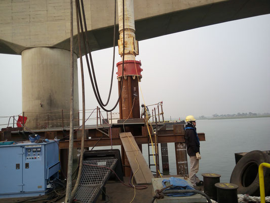
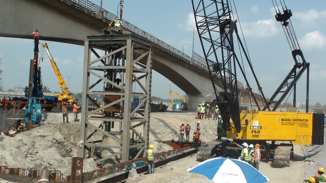
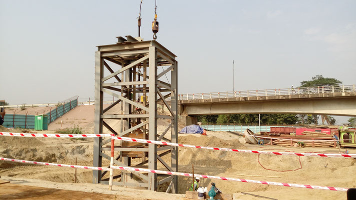
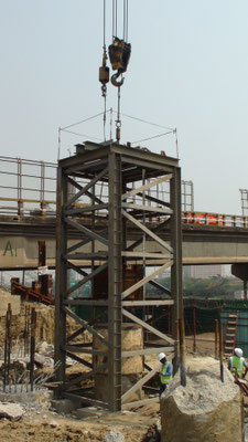
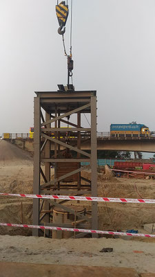
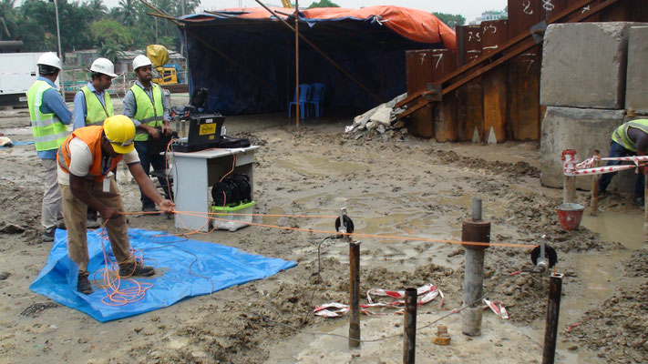
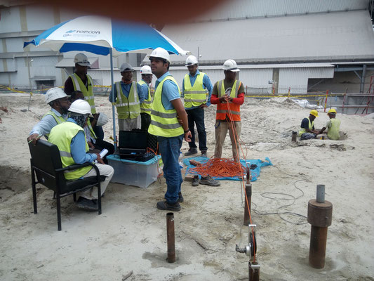
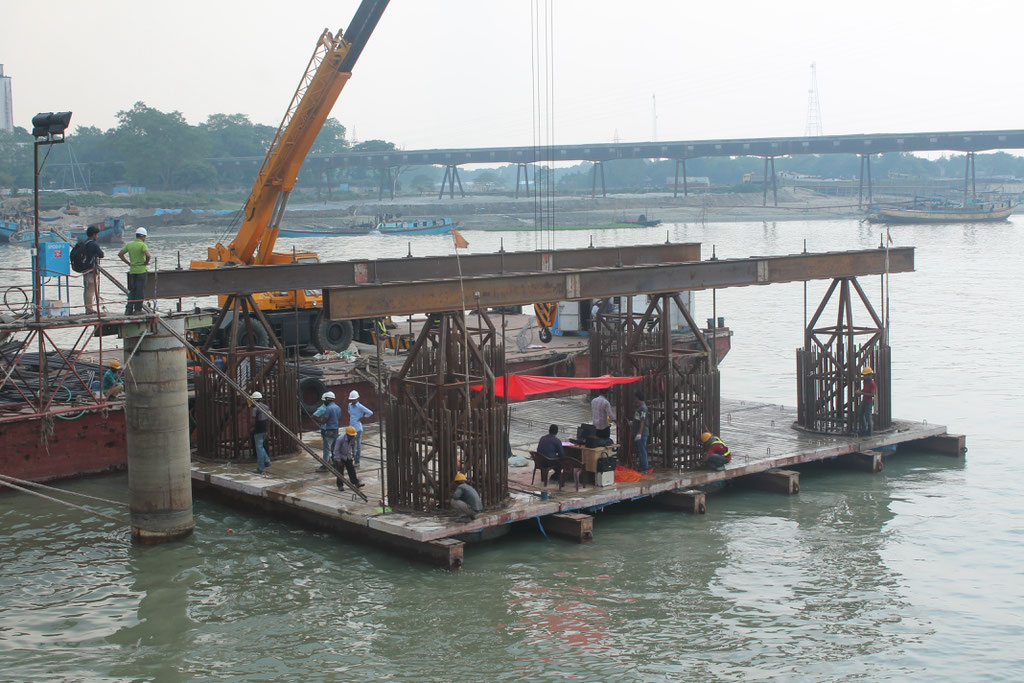
HIGH STRAIN PILE TESTING (Pile driving analyzer/ dynamic load testing)
PILE DRIVING ANALYZER
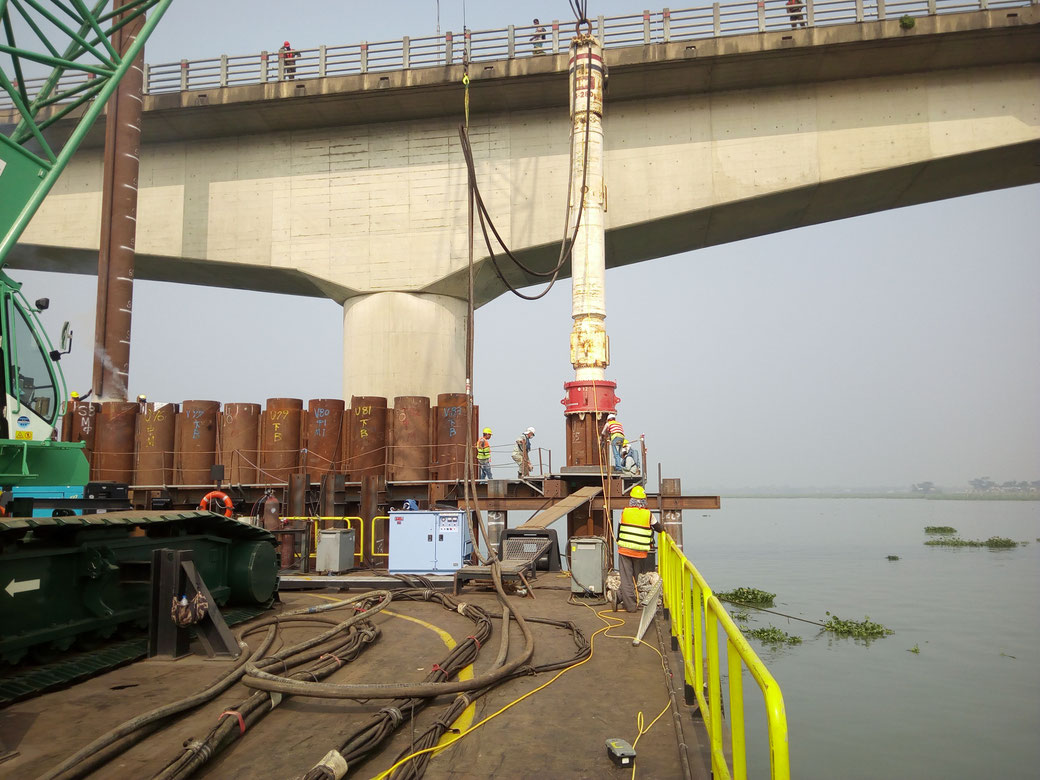
MEGHNA BRIDGE KANCHPUR BRIDGE GUMTI BRIDGE
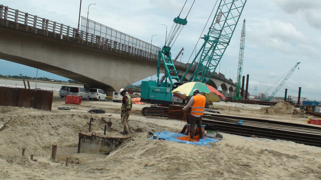
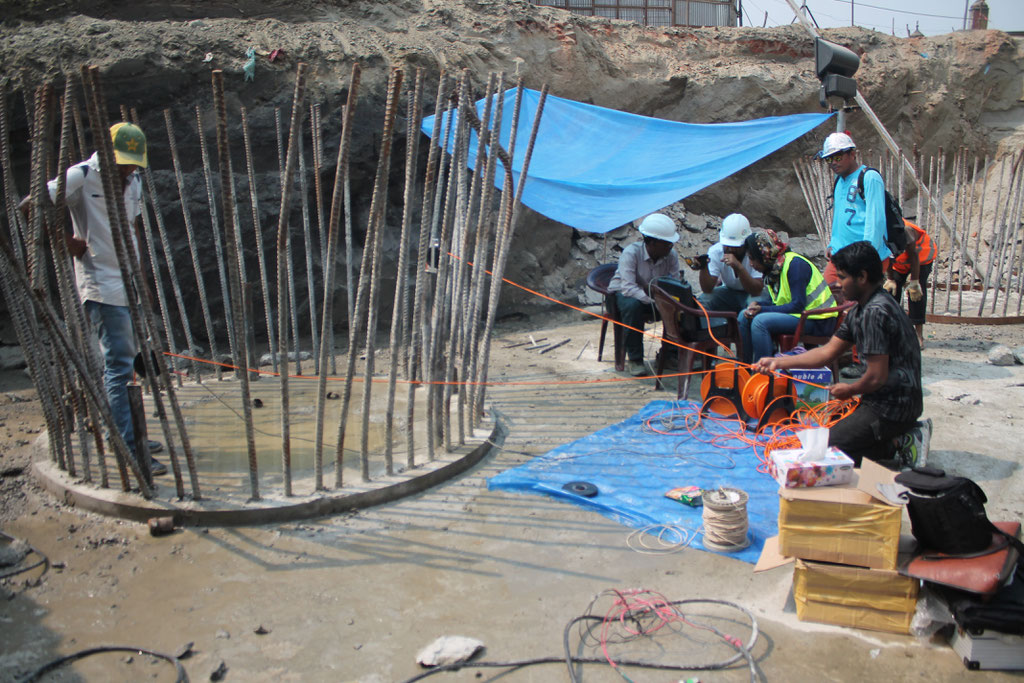
DYNAMIC LOAD TEST
GUMTI BRIDGE, OFF SHORE KANCHPUR BRIDGE MEGHNA BRIDGE
The concept of this test is to apply massive dynamic impact on the tested element and converting it into static capacity. The basic purpose of high strain dynamic pile testing is to evaluate pile
static capacity and its structural integrity using measurement of both force and velocity. Dynamic Load Test Wave Analysis Software (DLTWAVE) is used to analyze the field data interpreting the
dynamic wave and converting it into the required pile capacity.
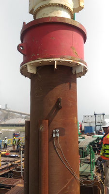
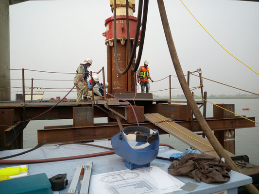
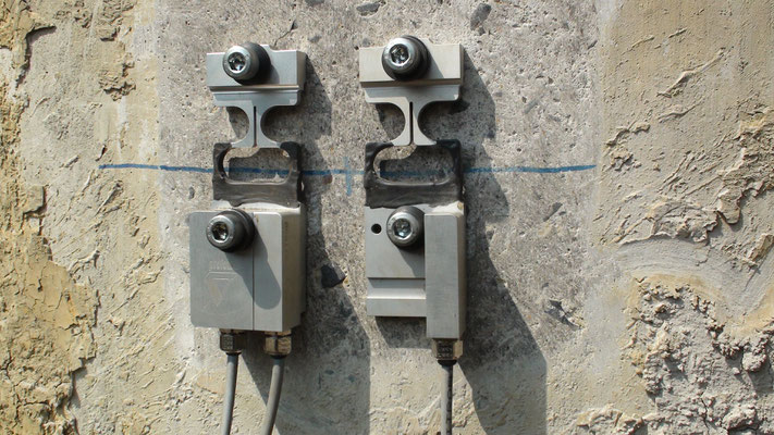
The method involves attaching a minimum of one pairs of strain transducers and one pair of accelerometers on diagonally opposite sides of the pile. These are fixed minimum 1.5 times the pile
diameter below pile top. Impact is generated using a hammer capable of delivering the required impact to achieve the required load. PROSOIL owns several hammers ranging form 3 tons to 25 tons.
The load and height of drop is pre-calculated using the soil parameters using DLTWAVE Equation Analyses and Drivability Studies (WEAP) analysis.
The strain transducers attached to the pile measure the strain on the piles’ body during impact, whereas accelerometers record the accelerations generated in the pile.
APPLICATIONS & BENEFITS
- Requires engineering and experienced judgment
- The setup of the test is time consuming and the hammer is not small and light
- The resistance to driving generated should be strong enough to mobilize pile ultimate resistance
- Reliability and accuracy of the results are related to the proficiency of the setup as well as the hammer drop
LIMITATIONS
|
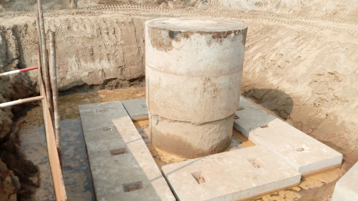
MECHANICAL CALIPER LOGGING (MCL)
The caliper tool measures the variation in bore hole diameter as it is withdrawn from the bottom of the hole, indicating any cave-ins or swelling in the hole.
Typically, the caliper arms are mechanically connected to a linear or rotary potentiometer such that a change in the angle of the arms causes changes in resistance. These changes in resistance
are proportional to average borehole diameter. In some probes, the voltage changes are converted to a varying pulse rate or digitized down hole to eliminate or minimize cable transmission noise.
Different arm length can be used to optimize sensitivity for the borehole diameter range expected. Vertical resolution of caliper measurements is a function of the size of the contact surface
(arm tip or pad); the response of the mechanical and electronic components; and digitizing interval used.
APPLICATIONS & BENEFITS
- Selection of arm lengths and angle, and tip diameter will affect sensitivity
- Shorter arms generally will provide more detail of the shape of the borehole wall than longer arms. However, size of caliper probe and borehole diameter may also determine arm lengths used
- Effected by the drilling fluids kept in the hole
- Continuous maintenance of the arms is required to enable easy movement of the arms
LIMITATIONS
|
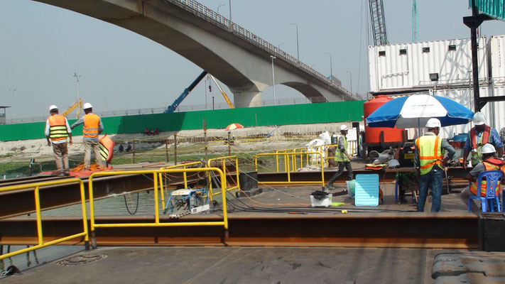
CROSS HOLE ULTRASONIC MONITORING (CHUM)
GUMTI BRIDGE, OFF SHORE KANCHPUR BRIDGE MEGHNA BRIDGE
GUMTI BRIDGE, ON SHORE
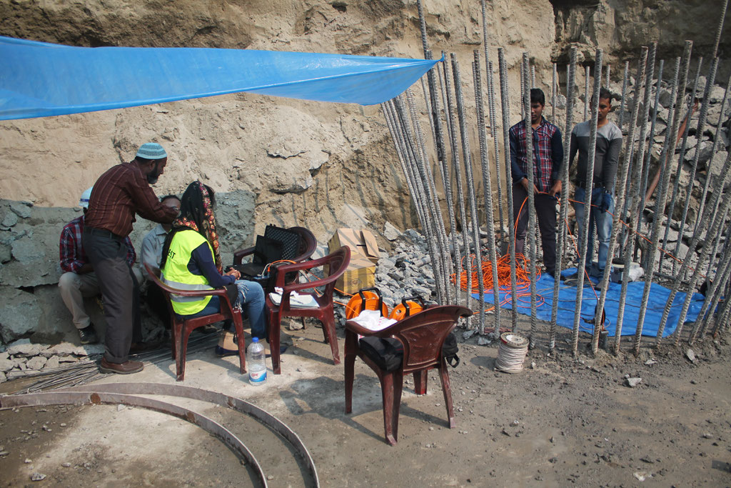
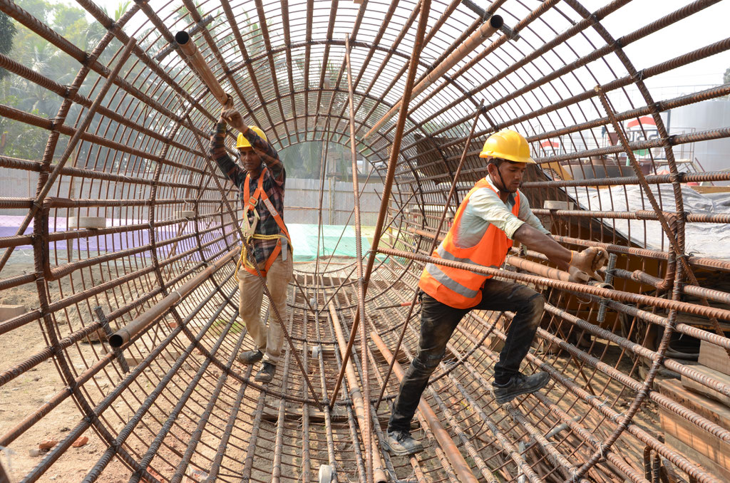
2ND BHAIROB RAILWAY BRIDGE
ULTRA SONIC TESTING
This method is particularly useful for large diameter pile foundations for major structures like river bridges, towers, initial piles (before load testing). The method is standardized as per ASTM D6760 and determines the quality and consistency of concrete between pairs of PVC or steel tubes (usually 38 -53mm and filled with water) pre-installed in bored piles, wall panels, concrete foundations. The output is in the form of waterfall map along with wave speed and energy or amplitude plot.
APPLICATIONS & BENEFITS
- Test carried out after 7 days from casting and can give early warning signs
- Sonic testing is intended to give information regarding pile lengths, homogeneity / integrity of concrete quality
- Able to locate defects in piles with regard to depth, character and severity
- Applicable for piles of flyovers, bridges, jetties, multi-storey buildings or where pile integrity is questionable
- Assessment of homogeneity / integrity of concrete in pile
- Non destructive
- Inexpensive
LIMITATIONS
- Access-tubes have to be pre-installed in the pile
- Does not address the question of pile capacity
- The number of access tubes affect the quality of the data and hence the interpretations
- Fabrication and installation of access tubes
https://www.youtube.com/watch?v=rizDhZbEI74&t=1s
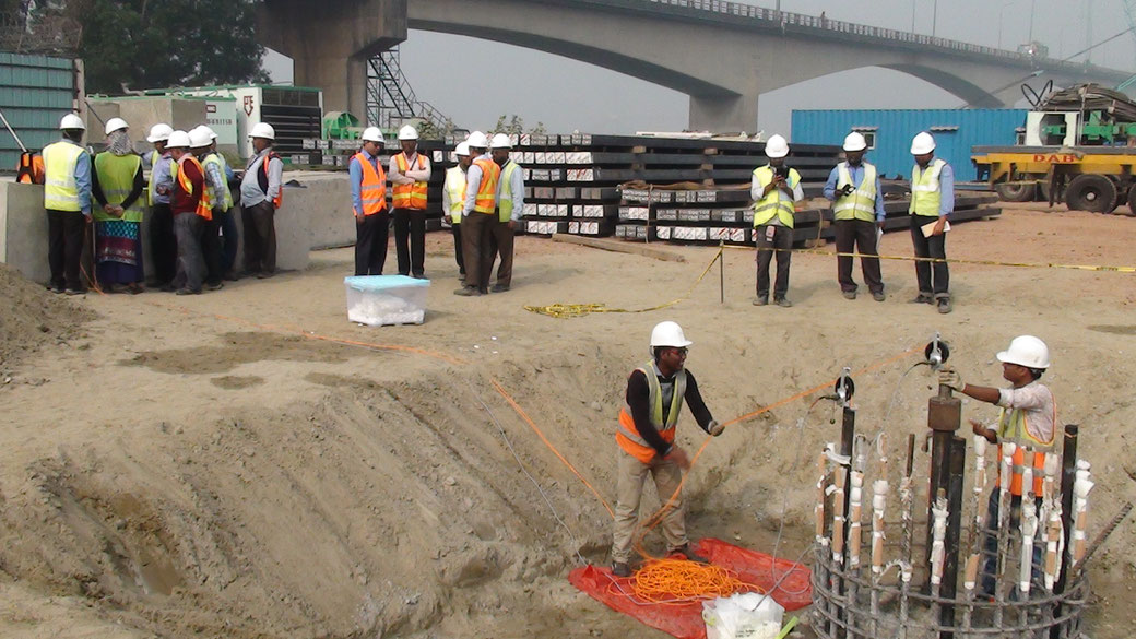
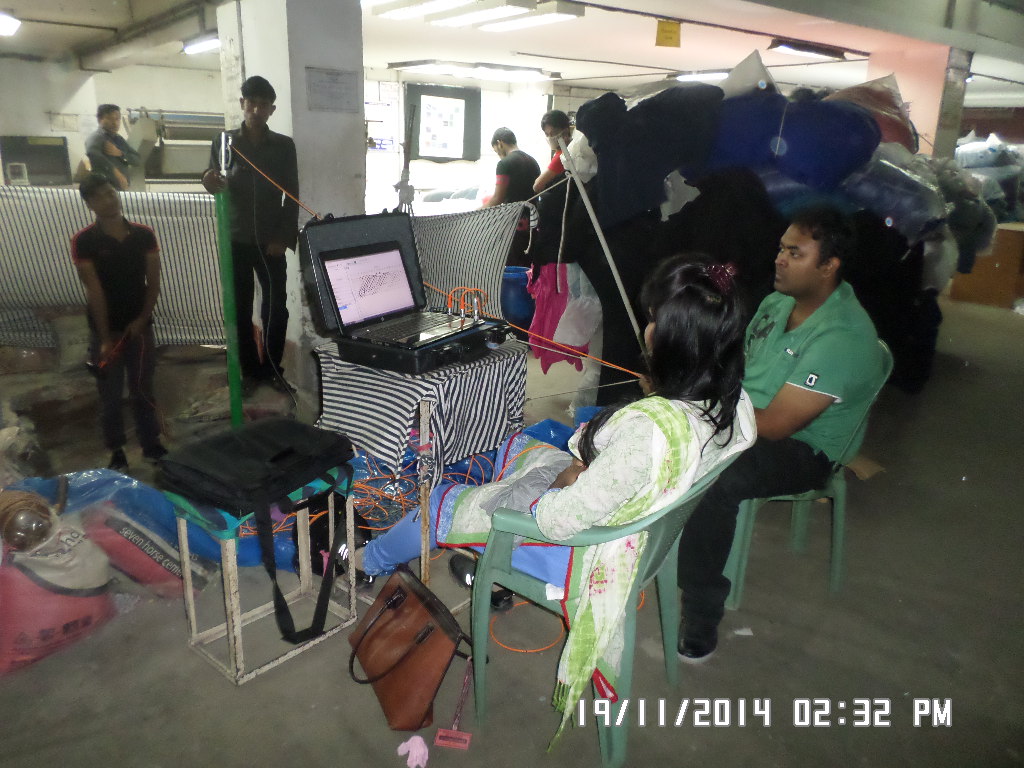
LOW STRAIN PILE TESTING (PILE INTEGRITY)
This method involves generation of a low stress wave with the help of a specialized hand held hammer. The waves are then collected in acceleration form by an accelerometer and integrated to velocity for further analysis. The accelerations generated by the impact are measured by the accelerometer attached on the pile top and are converted to velocity form for display onto the collector screen. Reflections from pile toe/pile discontinuities, cross-sectional changes, soil resistance changes, the wave speed through the pile etc., are graphically displayed. Since the strains during the test are of extremely low magnitude, the method is known as Low Strain Test method.
APPLICATIONS & BENEFITS
LIMITATIONS
|
PET Clip of Pile Integrity testing (i.e. in compliance with ASTM D5882-16) is in the following link
https://www.youtube.com/watch?v=AY-Rn1P6nYg&t=13s
|
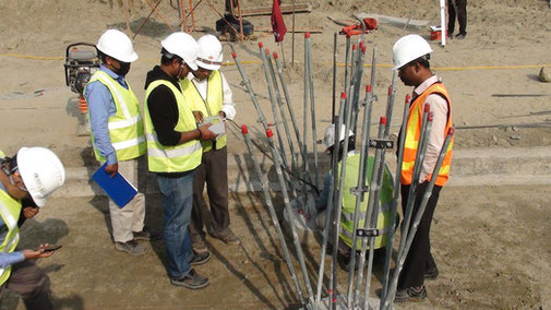
PARALLEL SEISMIC TESTING OF PILES
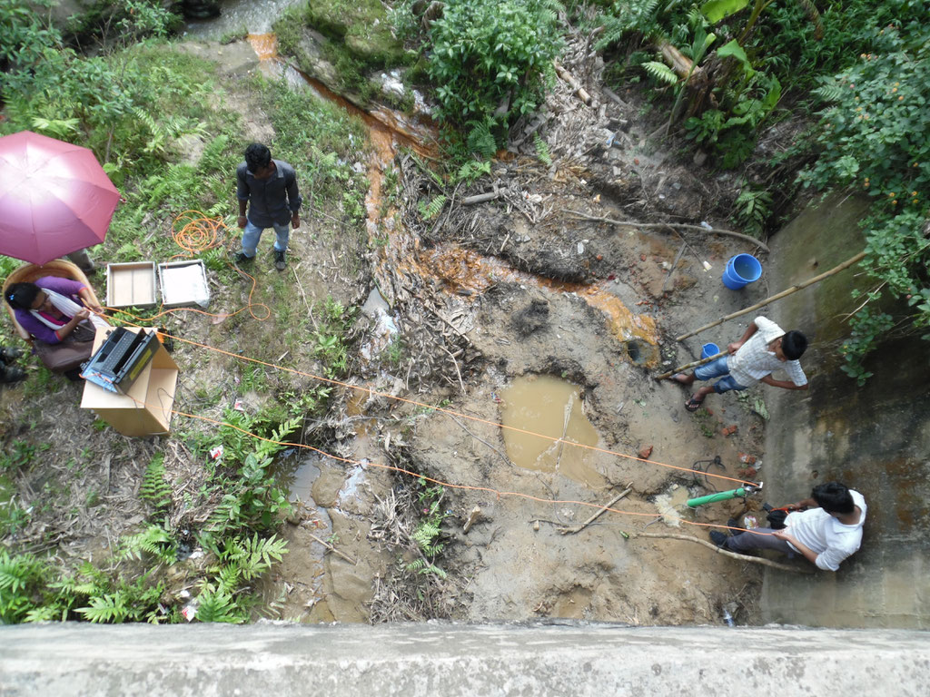
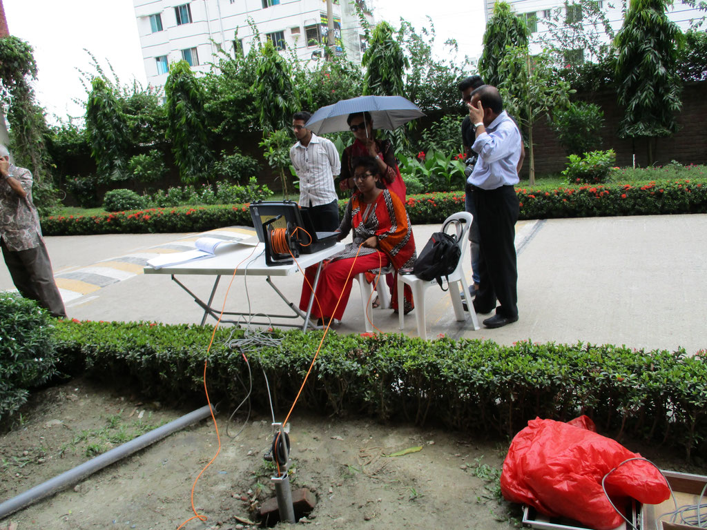
PSI uses the well-known Parallel Seismic method to establish the depth of existing foundations (specifically piles) where the superstructure precludes access to the pile heads.
The test requires the installation of a plastic access tube in parallel, and as close as possible, to the tested pile. The tube should be carried down to a depth exceeding the assumed pile length by a margin of 8-10 m and filled with water. In unsaturated soils the tube should be firmly grouted in the hole to achieve good coupling with the surrounding soil.
ProSoil Foundation Consultant
Laboratory: Sector 13, Road 14, Plot 79, Uttara Model Town, Dhaka
Registered Address:
88/B, Indira Road, Firmgate,
Dhaka-1215, Bangladesh
Mobile: +8801819218230, +8801707218230
e-mail: prosoil_9@hotmail.com, info@prosoil.org
web: www.prosoil.org

Copyright ©2020 PROSOIL FOUNDATION CONSULTANT.
All rights reserved