
PROSOIL is capable of conducting several tests aimed at the analysis of structures that can be applied to both old and new structures. For new structures, the principal applications are likely to
be for quality control or the resolution of doubts about the quality of materials or construction. The testing of existing structures is usually related to an assessment of structural integrity
or adequacy. The tests available for testing concrete range from the completely non-destructive, where there is no damage to the concrete, through those where the concrete surface is slightly
damaged, to partially destructive tests, such as core tests and pullout and pull off tests, where the surface has to be repaired after the test.
Non-destructive testing is usually carried out in the following situations:-
- to investigate the homogeneity of concrete mixing
- to determine the density and strength of concrete in a structure
- to determine the location of reinforcing bars and the cover over the bars
- to determine the number and size/diameter of reinforcing bars
- to determine the extent of defects
- to determine the location of in-built wiring, piping, ducting, etc
- to determine whether internal defects in concrete
- to determine if there is a bond between epoxy bonded steel plates and concrete members
- to determine the bonding strength of plaster
PROSOIL is continuously striving forward to use all the knowledge and equipment available to undertake NDT in order to get as much information as possible about structures.
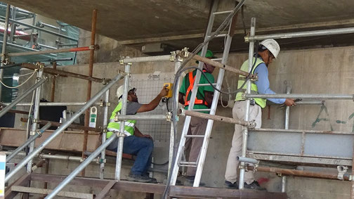
Rebar Scanning of existing structure
PROSOIL uses the The MALÅ CX ground penetrating radar (GPR) concrete scanning system to produce instant, high-resolution images, to provide a picture of the embedded
reinforcements - principally iron and steel. This information enables operatives to reduce drilling times, prevent costly impact on reinforcements and reduce wear and tear on drill
bits and cutting tools.
Using this battery-powered portable unit means we can also measure the size and depth of the embedded material as well as mapping the arrangement and position of reinforcing steel
bars, pre-stressing or post-tensioning tendons, steel conduit, and steel embedment.
The Ferroscan Covermeter can determine the size of a reinforcing bar embedded in concrete with an accuracy of about 10 per cent while the depth can be determined to 0.1 of an inch;
even up to a depth of six to seven inches.
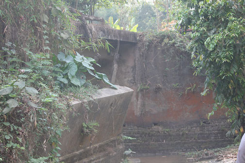
Visual inspection & Pre-conditional Surveys
Visual inspection is probably the most important of all non-destructive tests. It can often provide valuable information to the well trained eye. Visual features may be related to
workmanship, structural serviceability, and material deterioration and it is particularly important that the engineer is able to differentiate between the various signs of distress
which may be encountered. These include for instance, cracks, pop-outs, spalling, disintegration, color change, weathering, staining, surface blemishes and lack of uniformity.
Pre-condition surveys are an advanced programme of the visual inspection where the visual inspection is not confined only to the structure being investigated. It should also include
neighboring structures, the surrounding environment and the climatic condition. This extensive information is prepared in a detailed report to give a preliminary indication of the
condition of the structure and allow formulation of a subsequent testing programme.
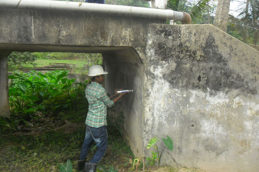
Schmit (Rebound) Hammer
The Schmidt rebound hammer is principally a surface hardness tester. It works on the principle that the rebound of an elastic mass depends on the hardness of the surface against which the mass impinges. There is little apparent direct theoretical relationship between the strength of concrete and the rebound number of the hammer. However, within limits, empirical correlations have been established between strength properties and the rebound number.
Although the rebound hammer does provide a quick, inexpensive method of checking the uniformity of concrete, it has some serious limitations. The results are affected by:
Carbonation Testing
Carbonation of concrete occurs when the carbon dioxide, in the atmosphere in the presence of moisture, reacts with hydrated cement minerals to produce carbonates, e.g. calcium carbonate. The carbonation process is also called depassivation. Carbonation penetrates below the exposed surface of concrete extremely slowly. The extent of carbonation can be determined easily by spraying a freshly exposed surface of the concrete with a 1% phenolphthalein solution. The calcium hydroxide is colored pink while the carbonated portion is uncolored.
The only limitation is the minor amount of damage done to the concrete surface due to drilling or coring.
Ultrasonic Testing
A pulse of longitudinal vibrations is produced by an electro-acoustical transducer, which is held in contact with one surface of the concrete under test. When the pulse generated is transmitted into the concrete from the transducer using a liquid coupling material such as grease or cellulose paste, it undergoes multiple reflections at the boundaries of the different material phases within the concrete. A complex system of stress waves develops, which include both longitudinal and shear waves, and propagates through the concrete. Measurement of the velocity of ultrasonic pulses of longitudinal vibrations passing through concrete may be used for the following applications:
It is possible to make measurements of pulse velocity by placing the two transducers on either:
Several factors have an effect on the results of this test which include:-
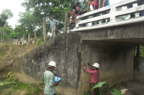
Cover Meter (Ferroscan) Scan
PROSOIL uses the Hilti PS200 Ferroscan Cover meter to produce instant, high-resolution images, to provide a picture of the embedded reinforcements - principally iron and steel. This information enables operatives to reduce drilling times, prevent costly impact on reinforcements and reduce wear and tear on drill bits and cutting tools.
Using this battery-powered portable unit means we can also measure the size and depth of the embedded material as well as mapping the arrangement and position of reinforcing steel bars,
pre-stressing or post-tensioning tendons, steel conduit, and steel embedment.
The Ferroscan Covermeter can determine the size of a reinforcing bar embedded in concrete with an accuracy of about 10 per cent while the depth can be determined to 0.1 of an inch; even up to a
depth of six to seven inches.
Temperature Monitoring of Concrete
Temperature of concrete can be monitored manually by means of a special thermometer or automatically by the use of thermocouples connected to a data acquisition system.
MANUALLY: A thermometer is kept in contact with the fresh concrete element in order to attain the temperature of the concrete. In the case of measuring the temperature of concrete during the
curing stage, a thermocouple node is embedded within the concrete element and extended outside that element whilst being insulated from the ambient temperature and the thermometer is used to
attain the temperature of the concrete.
AUTOMATICALLY: A thermocouple is a temperature sensor formed by connecting wires of two dissimilar metals together. A temperature gradient between the ends of the wires generates a small DC
voltage which is directly proportional to temperature. The sensitivity available depends on the materials used to make the thermocouple. They are ideal for applications where the probe is not
recoverable such as embedded in a material like concrete or at great depths below the ground surface.
These thermocouples are embedded within the concrete prior to casting by binding them to the reinforcement bars. Installed at several locations within the same element, these thermocouples can
provide an idea on the heat of hydration within the monitored element and provide information on the temperature gradients of the monitored element. The data is collected in-situ by means of a
data acquisition system that logs the voltage difference within each thermocouple node.
Slab Load Test
As part of testing and assessing the performance of a cast slab whether it is a hollow or solid slab, one or two way slab, weights are place on top of the slab to measure its performance. By monitoring the deflection of the tested element (slab), assessment of the slab can be made and whether the structural performance of the slab is within the design criteria that it was designed for.
The slab is loaded to its design load by placing dead loads in the form of cement bags or concrete blocks or any other source of load. Loading is usually carried over a period of 2 days at
various loading schemes during which the deflection of the slab is monitored at various location within the loaded area.
Core Cutting
The purpose of core testing is to assess the concrete quality, deterioration and workmanship involved in batching, mixing, placing, compacting and curing of concrete. Cores are obtained from the element to be assessed using a HILTI DD 250 E Coring Machine using a diamond bit. Drilling water coolant is used to reduce friction during the coring.
With the use of the Ferroscan “Hilti PS 200”, the cores can be drilled within interfering with the steel reinforcement embedded within the tested element.
Pull-Out
A pullout test measures the force required to pull a specially shaped steel rod or disc out of the hardened concrete into which it has been cast. The procedure requires the steel rod to be tested to be gripped using an attachment that is connected to a hydraulic jack. Once connected force is applied to the hydraulic jack until failure of the bond strength between the embedded steel and the cast element or until the load exceeds the design requirements without showing any signs of failure.
Pull-Off
The pull off test is based on a concept that the force required for pulling a metal block, together with a layer of concrete or mortar, from the surface to which it has been attached, is related to the strength of the concrete.
The technique may be applied in two forms:-
- If a block is attached directly to the surface then the stressed volume of concrete lies close to the face of the block.
- Alternatively the test may be carried out by partially coring the concrete and bonding a block of the same nominal diameter to the top of the cylinder of concrete thus isolated.
ProSoil Foundation Consultant
Laboratory: Sector 13, Road 14, Plot 79, Uttara Model Town, Dhaka
Registered Address:
88/B, Indira Road, Firmgate,
Dhaka-1215, Bangladesh
Mobile: +8801819218230, +8801707218230
e-mail: prosoil_9@hotmail.com, info@prosoil.org
web: www.prosoil.org
Copyright ©2020 PROSOIL FOUNDATION CONSULTANT.
All rights reserved