
Instrumentation works involve the analysis of structure / ground conditions during the construction work to report any variation to the original condition.
Installed equipment placed in the ground and on the existing structures and roads located around the construction site of the proposed development aid to monitor any change or any abrupt behavior
of such during the monitoring period during construction. In this light, data and information has to be periodically measured. Data integrity and periodic monitoring frequency is vital to the
reliability of the report to serve its purpose of allowing construction works to be economically and safely built.
PROSOIL has several techniques and methods of monitoring and installation based on the site conditions and requirements. The idea is to develop an understanding
to the ground / structure behavior based on a combination of installations of instrumentation equipment that monitor that behavior. The instrumentation report consists of data and graphical
presentation of data collected on site. The report is periodically done and delivered to the client for use as basis of monitoring their site construction activities and it’s effect on the
neighboring structures as well as the sub-surface.
INCLINOMETERS
The purpose of inclinometer monitoring is to observe and monitor any lateral movements within structures or strata and analyze whether remedial works are required to subdue any such movements. Applications for vertical inclinometers include:
- Monitoring slopes and landslides to detect zones of movement and establish whether movement is constant, accelerating, or responding to remedial measures.
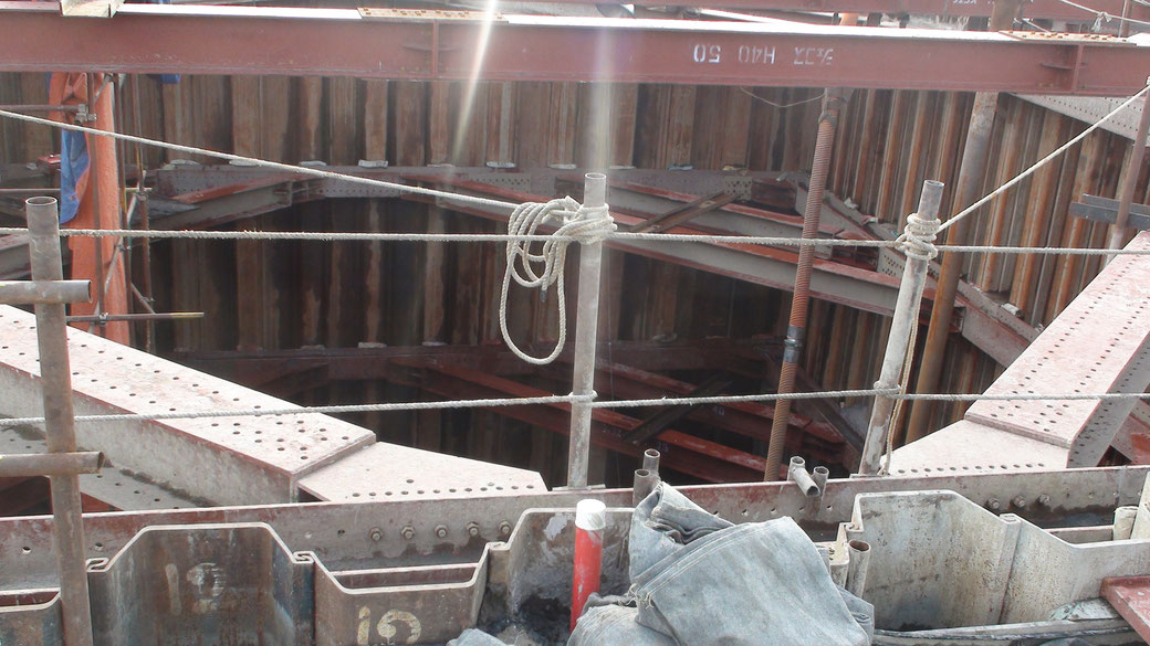
- Monitoring diaphragm walls and sheet piles to check that deflections are within design limits; that struts and anchors are performing as expected, and that adjacent buildings are not affected by ground movements.
- Monitoring dams, dam abutments, and upstream slopes for movement during and after impoundment.
- Monitoring the effects of tunneling operations to ensure that adjacent structures are not damaged by ground movements.
There are two types of inclinometers available, which are:-
-
Portable Inclinometer Probe
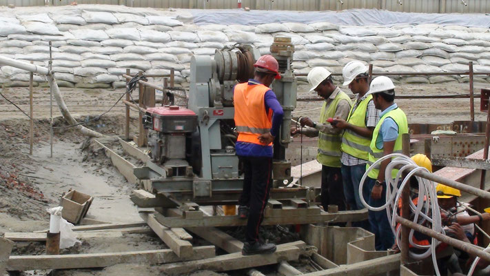
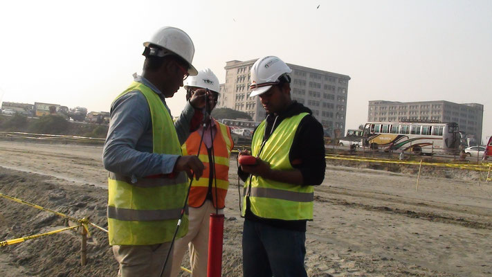
The portable inclinometer is more robust and can be moved from one monitoring point to another. The concept lies in lowering a probe into a pre-installed casing pipe, in the ground, pile, shoring wall, or any other structure that is being monitored to periodically check for lateral movements of the structures. The readings are compared to previous initial readings in order to assess the lateral movement and its extent. PROSOIL currently uses two portable probes designed by Roctest and Encardio-Rite.
- In place Inclinometer Probe
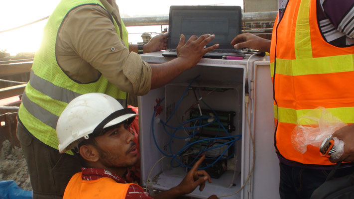
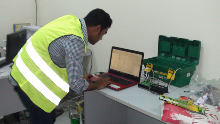
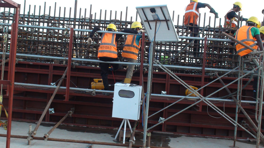
The in-place inclinometers are installed in location where real-time and constant monitoring is required. As the name of the system implies, it is installed in one-place only and continuously monitors the lateral movement of that location. The system comprises of access rods connecting several in-place inclinometer probes connected to a data acquisition system and the ground.
- In place Inclinometer Probe
GUMTI BRIDGE KANCHPUR BRIDGE DHAKA MRT DEPOT DHAKA MRT DEPOT
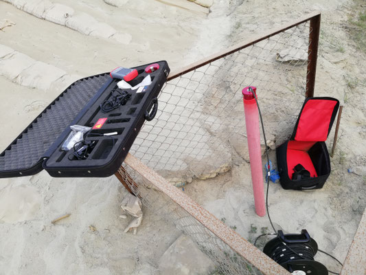
BIT—BOREHOLE INCLINATION TESTER
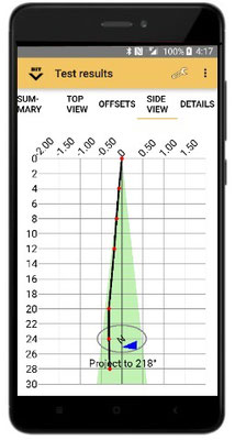
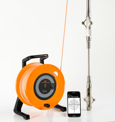
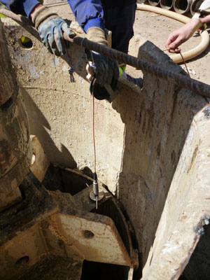
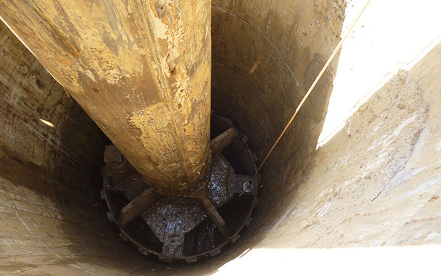
All piling specifications prescribe the allowable deviation of the pile axis from the vertical. Typical limits vary between 1.33% (UK ICE) and 2% (US FHWA). In diaphragm and secant pile walls,
the specification is typically even more restrictive. Unlike traditional systems, BIT uses the auger/bucket itself as a centralizer, thus eliminating the need for a bulky system. The BIT enables
fast and accurate determination of inclination in both dry and wet boreholes, vertical or raked. Large boreholes and diaphragm-walls may be quickly tested several times during drilling to enable
real-time corrective action. Finished pile inclination can be measured through
the CSL access tubes.
It is compatible with the NEW ASTM standard for inclination measurement of boreholes and piles ASTM D8232-18
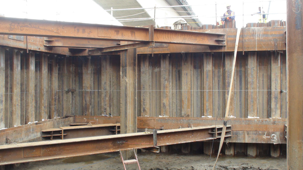
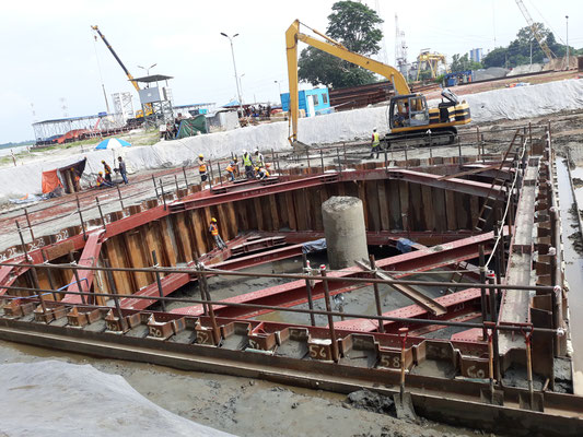
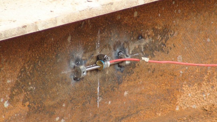
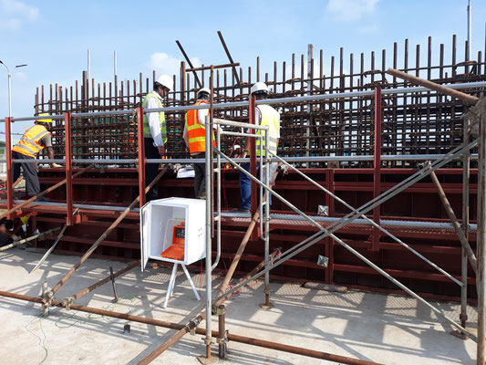
STRAIN - GAUGES FOR DEEP EXCAVATION MONITORING
Meghna Bridge
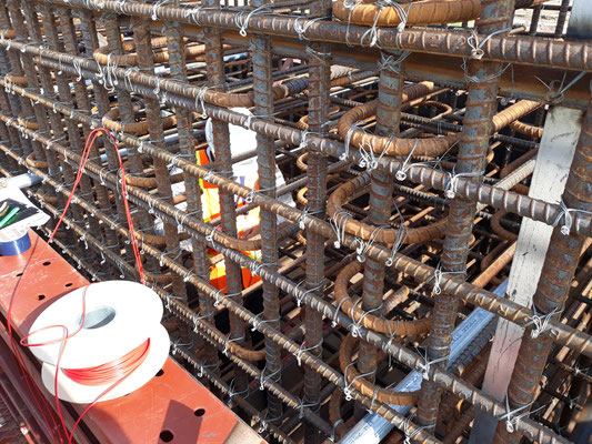
CONCRETE STRAIN GAUGE FOR MONITORING STRAIN DURING CURING PERIOD
Strain gauges are attached directly to the surface of the structure or are embedded within the structure to sense the extension and compression in the structure itself. Each strain gauge consists
of two end blocks with a tensioned steel wire between them. As the strain gauges undergo strain, the end blocks will move relative to each other. The tension in the wire between the blocks will
change accordingly, thus altering the resonant frequency of the wire. Vibrating wire readout is utilized to generate voltage pulses in the magnet / coil assembly located at the center of the
strain gauge. The magnet / coil assembly plucks the wire and measures the resulting resonant frequency of vibration.
The uses of strain gauges are continuous as they are robust and can be deployed / used in any environment and circumstance. Generally, strain gauges are used in pile instrumentation and strut
monitoring, however they may also be used to measure stresses in raft foundation and columns.
TEMPERATURE MONTORING OF CONCRETE
THERMO COUPLE INSTALLATION AND MONITORIN
Temperature of concrete can be monitored manually by means of a special thermometer or automatically by the use of thermocouples connected to a data acquisition system.
MANUALLY: A thermometer is kept in contact with the fresh concrete element in order to attain the temperature of the concrete. In the case of measuring the temperature of concrete during the
curing stage, a thermocouple node is embedded within the concrete element and extended outside that element whilst being insulated from the ambient temperature and the thermometer is used to
attain the temperature of the concrete.
AUTOMATICALLY: A thermocouple is a temperature sensor formed by connecting wires of two dissimilar metals together. A temperature gradient between the ends of the wires generates a small DC
voltage which is directly proportional to temperature. The sensitivity available depends on the materials used to make the thermocouple. They are ideal for applications where the probe is not
recoverable such as embedded in a material like concrete or at great depths below the ground surface.
These thermocouples are embedded within the concrete prior to casting by binding them to the reinforcement bars. Installed at several locations within the same element, these thermocouples can
provide an idea on the heat of hydration within the monitored element and provide information on the temperature gradients of the monitored element. The data is collected in-situ by means of a
data acquisition system that logs the voltage difference within each thermocouple node.
GROUND SETTLEMENT POINT
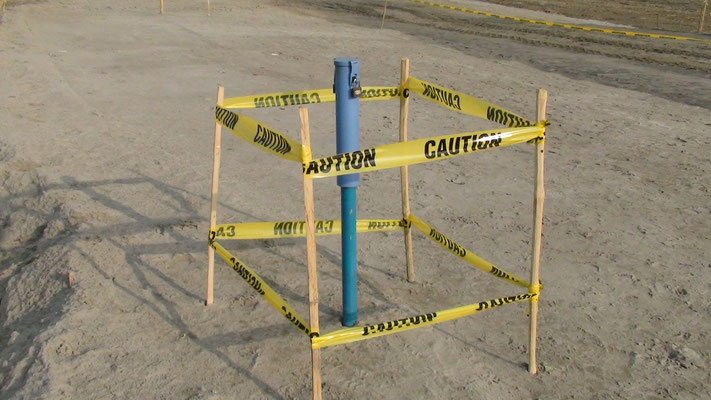
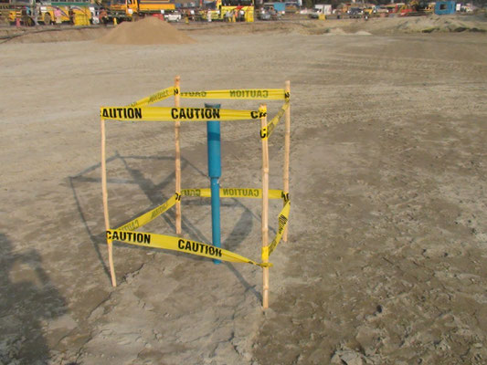
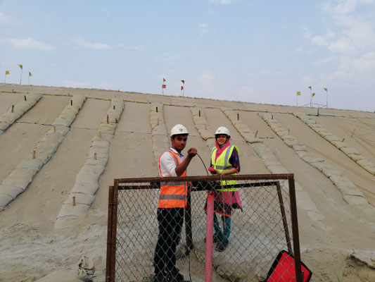
The ground settlement point is used to monitor the vertical settlement on the surface of embankments, soil, masses, etc. It may also serve as a deep ground settlement point for monitoring of vertical displacement of utilities and in some cases as a benchmark.
VIBRATION MONITORING
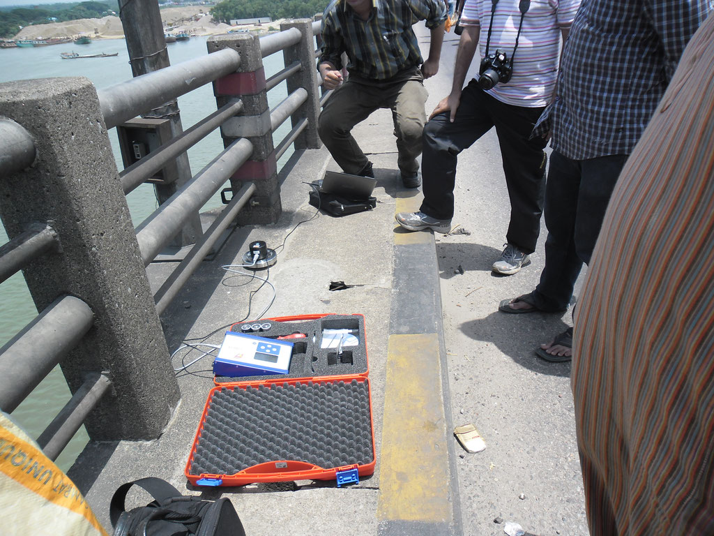
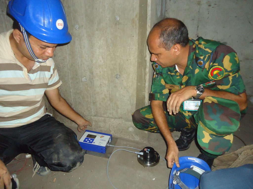
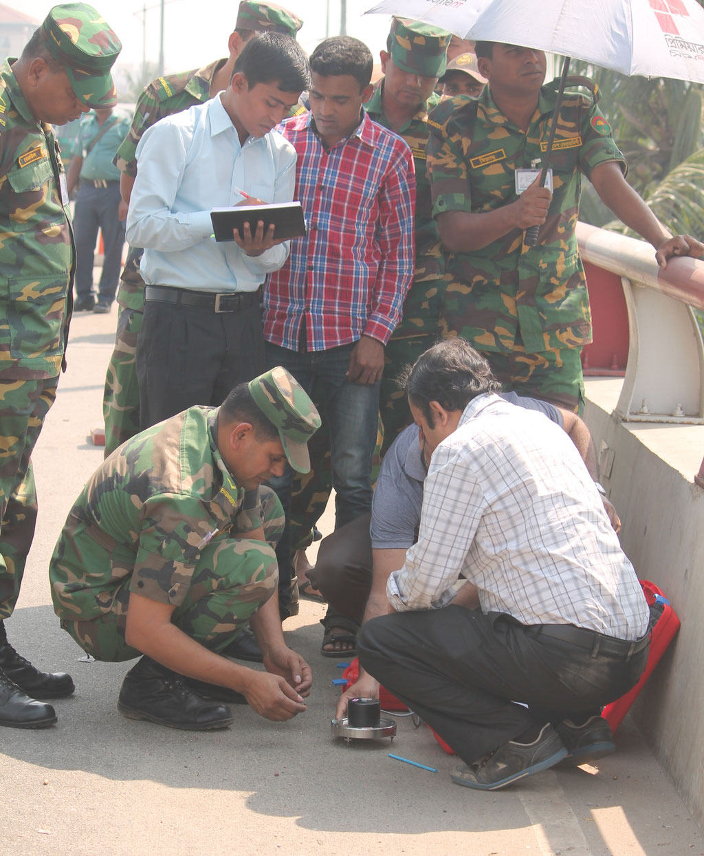
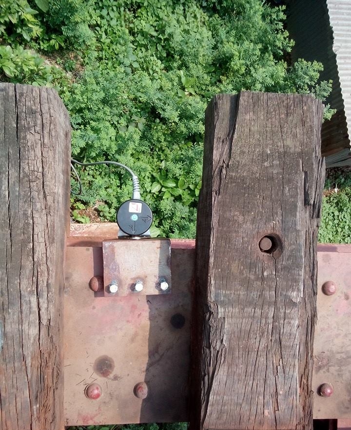
Vibration monitoring is a measurement of vibration and its effect on the nearby elements surrounding a particular structure. It is empirical to clearly understand the proper procedures on how the measurements should be made and how the acquired data must be properly evaluated. PROSOIL uses the Profound Vibra which offers the most advanced monitoring technology available with unequaled versatility and flexibility. As a smart device, the vibration monitoring instrument can record threshold values or give warning beyond certain limits and records data at required intervals.
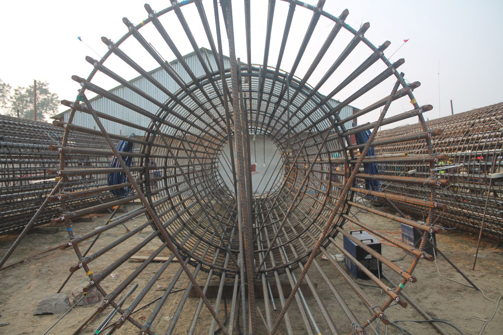
STATIC MAINTAINED LOAD TEST FOR BORED PILE FOUNDATION MONITORING WITH DISTRIBUTED FIBRE OPTIC SENSOR (BOTDA)
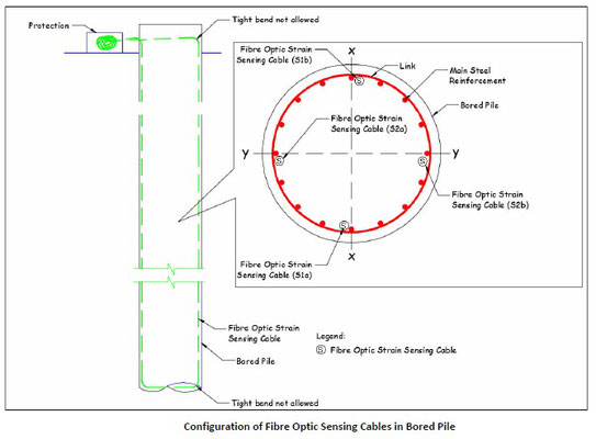
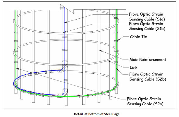
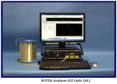
Recent advancement in photonics and optoelectronic devices has led to new applications of fibre-optic sensors in the field of civil engineering. The advantages of fibreoptic sensors include geometrical adaptability, dual task of sensor and path for transmission of the signal, precision and sensitivity over large measurement ranges, and immunity to electromagnetic interference and electrical hazard. Distributed optical fibre strain sensing is one of the many types of optical fibre technology that have been increasingly applied in geotechnical fields such as piled foundations, retaining walls, and tunnels. The novelty of this technology is that a single optical fibre can sense over its full length of the cable (potentially up to 50 km long) against any strain and temperature changes. This means a single optical fibre can replace thousands of point-wise strain gauges and potentially provide an economical method to monitor deformation of large or long extended structures where previously this was impractical due to their size, complexity, location or environment. Moreover, distributed strain sensing is often considered more important than having a very accurate localized strain sensor but limited in numbers particularly when evaluating the interaction of forces between the structure and the soil.
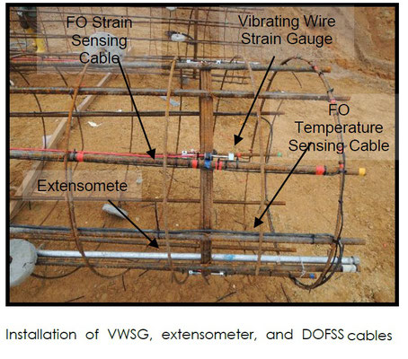
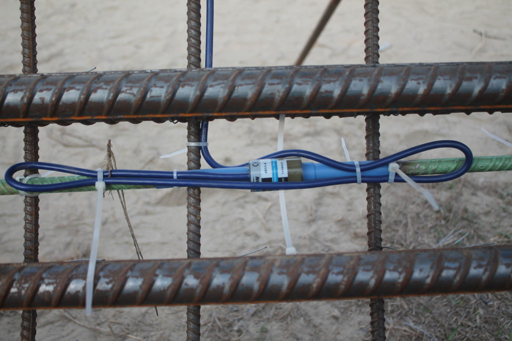
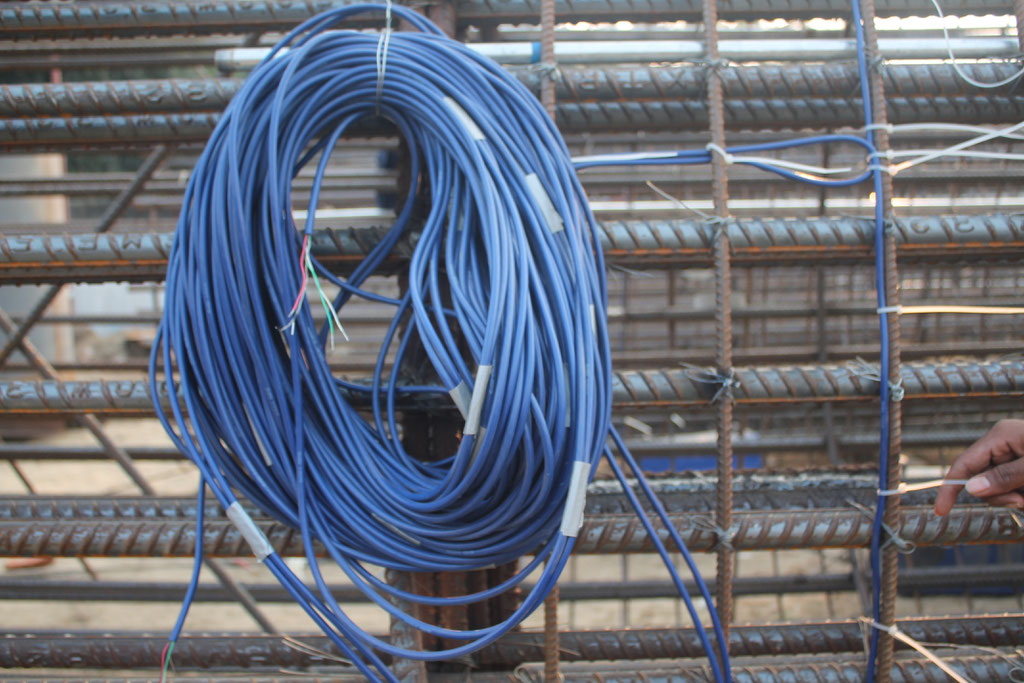
BORED PILE WITH STRAIN AND TEMPERATURE MEASUREMENT BY VIBRATING WIRE STRAIN GAUGES

CRACK METER – CRACK GAUGE
A) Tell-Tale Crack Meter
The system consists of two plates that overlap for part of their length. One plate is calibrated in millimeters and the overlapping plate is transparent and marked with a hairline cursor. As the crack width opens or closes, one plate moves relative to the other. The relationship of the cursor to the scale represents the amount of movement occurring. These gauges are monitored over time, whilst being kept as far away from human disturbance as possible, to develop an understanding in the width and direction of movement of the crack.
B) Crack Micro-scope A simple hand held tool that aids in the identification of crack width. It comes in the form of a simple microscope with a lighting element.
BUILDING SETTLEMENT MARKER
The building settlement marker is used to monitor the vertical settlement / movement of any structure. These reflective markers can be monitored either using total-station or digital level equipment for the most precise readings.
BUILDING SETTLEMENT POINT
The building settlement point is to be embedded / fixed to a vertical member to monitor the vertical settlement / movement of any structure. It consists of a male anchor fitted onto the anchor socket which in place is usually embedded / fixed in a column / wall of thickness greater than 80mm. These points are best monitored using digital level equipment for the most precise readings.
GROUND SETTLEMENT POINT
The ground settlement point is used to monitor the vertical settlement on the surface of embankments, soil, masses, etc. It may also serve as a deep ground settlement point for monitoring of vertical displacement of utilities and in some cases as a benchmark.
PAVEMENT MARKERS
The pavement / tarmac settlement point is used to monitor the vertical settlement of any horizontal member (asphalt pavement, road, concrete slab, etc.). The set-up consists of a plastic tapered disc (1) around 100mm in diameter held in place by a special retaining nail (2).
PORTABLE TILT METER
Portable tilt meters are mainly used to monitor buildings, structures, utilities, etc. as well as the inclination and rotation of retaining walls, dams, piers, piles, etc. It may also be used to evaluate the performance of bridges, struts and the stability of structures in land slide areas.
The main advantages of the portable tilt meter systems are the following:
- The manner of installation of the tilt plates is very simple and may be screwed or bonded to the structure.
- One tilt meter may be used to monitor many bronze tilt plates.
- The tilt plate is made of bronze which is rugged in construction and has excellent temperature stability.
The portable tilt meter is suitable for monitoring change in inclination of a structure. Tilt meter consists of a basic sensor housed in a rugged frame with machined surfaces that facilitate accurate positioning on the tilt plate. The bottom surface is used with horizontally mounted tilt plates and the side surfaces are used with vertically-mounted tilt plates.
STRAIN - GAUGES
Strain gauges are attached directly to the surface of the structure or are embedded within the structure to sense the extension and compression in the structure itself. Each strain gauge consists of two end blocks with a tensioned steel wire between them. As the strain gauges undergo strain, the end blocks will move relative to each other. The tension in the wire between the blocks will change accordingly, thus altering the resonant frequency of the wire. Vibrating wire readout is utilized to generate voltage pulses in the magnet / coil assembly located at the center of the strain gauge. The magnet / coil assembly plucks the wire and measures the resulting resonant frequency of vibration.
The uses of strain gauges are continuous as they are robust and can be deployed / used in any environment and circumstance. Generally, strain gauges are used in pile instrumentation and strut
monitoring, however they may also be used to measure stresses in raft foundation and columns.
CENTER - HOLE LOAD CELL
Center hole load cells theory of functioning is similar to that of the strain gauges, however these load cells serve in monitoring the loads in the anchors or tie backs.
ProSoil Foundation Consultant
Laboratory: Sector 13, Road 14, Plot 79, Uttara Model Town, Dhaka
Registered Address:
88/B, Indira Road, Firmgate,
Dhaka-1215, Bangladesh
Mobile: +8801819218230, +8801707218230
e-mail: prosoil_9@hotmail.com, info@prosoil.org
web: www.prosoil.org

Copyright ©2020 PROSOIL FOUNDATION CONSULTANT.
All rights reserved